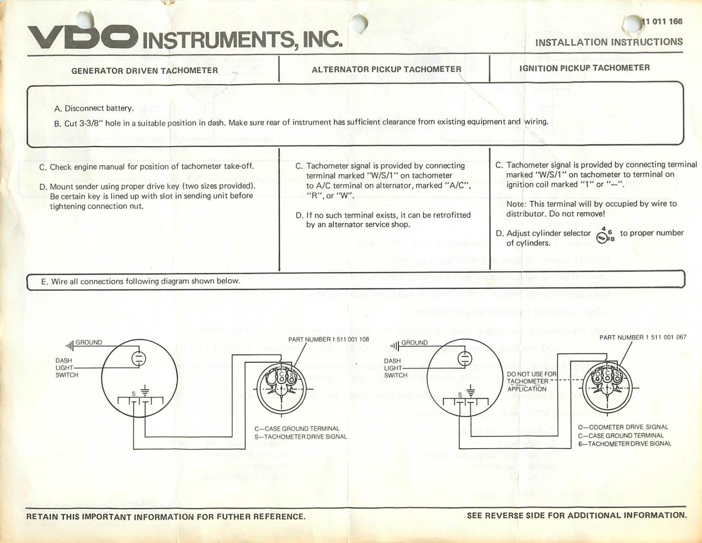
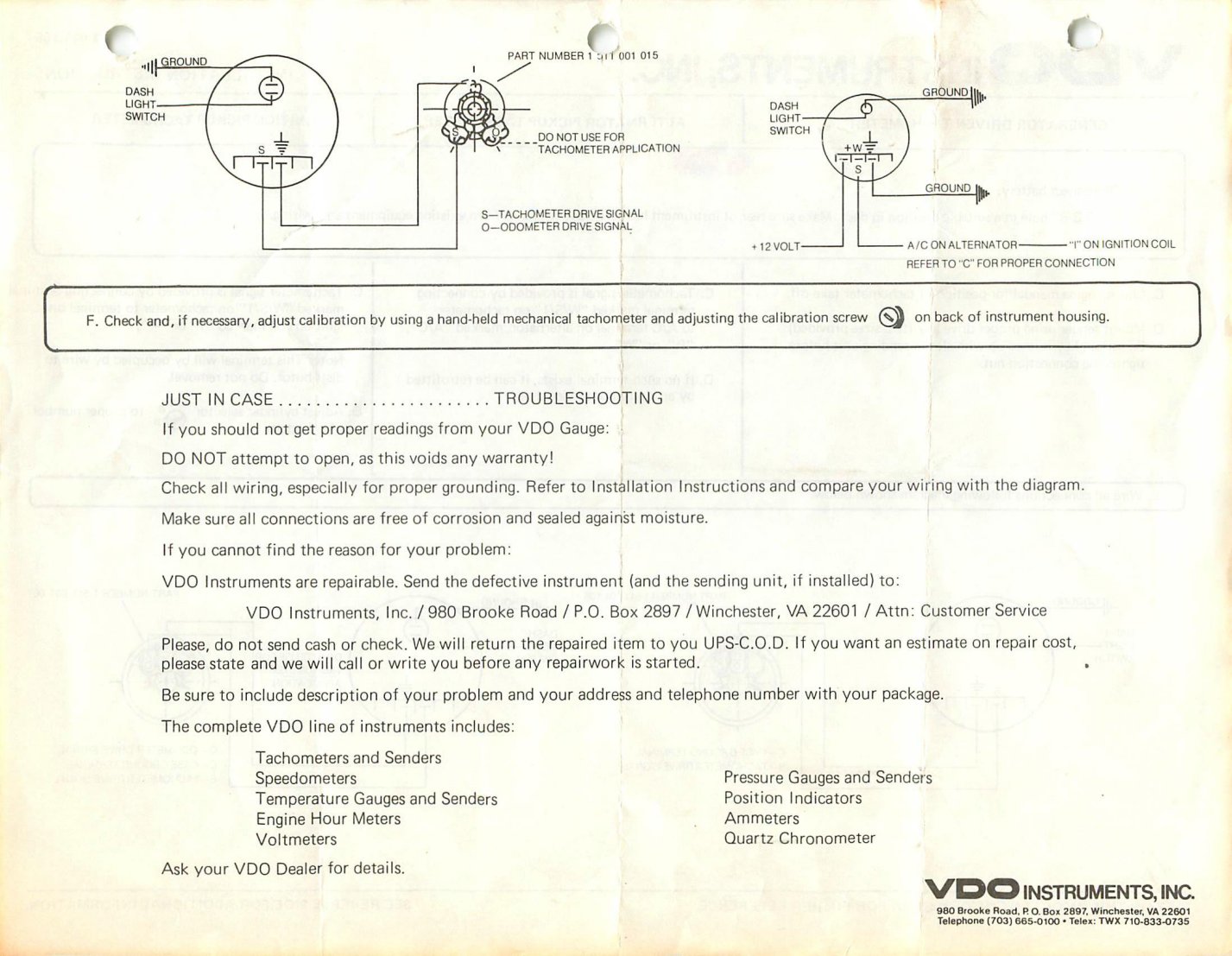
Diagram Old Vdo Tachometer Wiring

Auto meter vdo equus etc.
Diagram old vdo tachometer wiring. Remove the key from the ignition and disconnect the negative terminal from the battery post. Read these instructions thoroughly before making installation. Use pot to calibrate. Vdo tachometer is not included.
Part numbers forhe t vdo generator sensor is part 340 001 vdo s inductive sensor is part 340 020 1. Please understand that proper wiring must be maintained throughout your. Old vdo tacho diagram. Standard resistive gauges 52mm 12 24 volt retrofit kit temperature pressure level trim 2013 temperature resistance chart 2004 viewline 52mm wiring diagram 2014 viewline standard resistive gauges 52mm installation sheet 2014 viewline temperature gauges 12 24 volt 2011 viewline temperature gauges 52mm 2008.
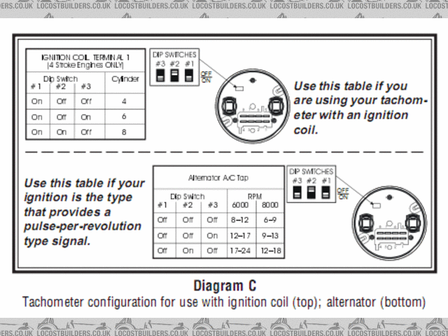
Measuring instruments vdo tachometer with counter installation instructions manual 11 pages measuring instruments vdo cancockpit series product manual. New generation 2009 flexible instrumentation with can bus technology 174 pages. Adjust the potentiometer on the back of the tach. I have the wiring dip switch diagram for 333 351 and 333 354 tacho s.
Always disconnect battery ground before making any electrical connections. This sensor is avail able from your auto parts dealer. Related manuals for vdo tachometer. Do not deviate from assembly or wiring instructions.
Use this table if you are using your tachom eter with an ignition coil. 4000 rpm alternator tach 2 1 ratio set for 6 cyl. Diagram f fine adjustment of the vdo tachometer when used with an alternator compare the vdo tachometer reading with that of a reference tachometer. Diagram e proper wiring of the vdo programmable tachometer with typical ignition systems ˇˆ ˇ.
Signal wire connects to a line between coil negative and contact point. When the vdo tachometer reading. Use a wrench to tighten the nuts until the tachometer can not longer be rotated by hand. I tried it in my 300tdi it s out of my old race car but still reads high even after adjusting the internal pot.
As on the schematic the positive wire from the tachometer is connected to the ignition switch. Wiring diagram for aftermarket tachometer. I can scan it if it s the right one. Reattach the mounting cup then mount the keypad in the location of your choice.
8 pin connection f1 fuse 5a quick response c1 8 pin mqs connector you must comply with the. Wiring the tachometer 1. For more details the following schematic illustrates three main wires of tachometer wiring. Tachometer without display 13 gb 14 connector set 8 pin a2c59510850 30 terminal 30 steady state plus 12 v 15 terminal 15 connected ignition plus 58 terminal 58 lighting 31 terminal 31 ground designations in the wiring diagram.
Wire the tachometer to the vehicle as shown in diagram h on page 4. Al or the spot where the negative battery fuse box. I have this vdo tacho 80 odd mm unused but i have mislaid the instructions.


