Smartcraft Nmea 0183 Wiring Diagram

Smartcraft Nmea 0183 Wiring Diagram Wiring Diagrams
Lowrance Nmea Cable Wiring Diagram Diagram Base Website Wiring

Pin On Car Diagram
Smartcraft Wiring Diagram H1 Wiring Diagram
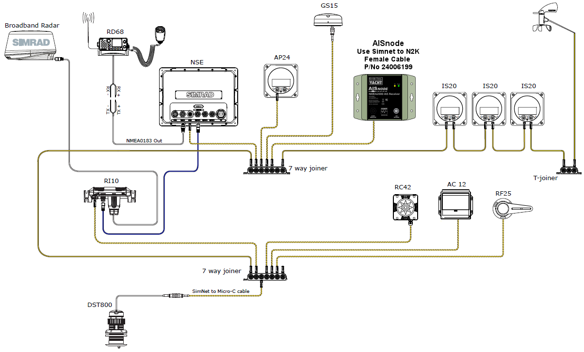
Connecting Our New Aisnode Receiver To A Simrad Network Digital
Mercury Smartcraft Wiring Diagram H1 Wiring Diagram

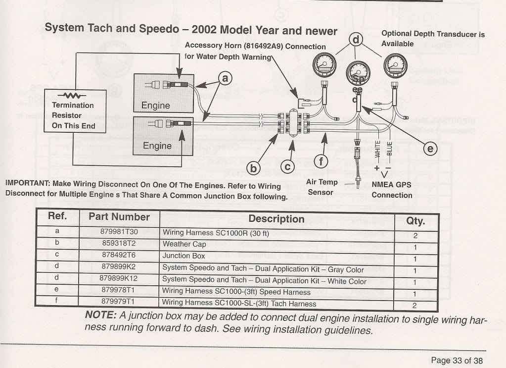
A wire retainer b wire terminal c connector d assembled components e transducer connector.
Smartcraft nmea 0183 wiring diagram. Smartcraft depth transducer wiring connections page 2 5 90 8m0063595 december 2011 2. First look at the gps wiring diagram and determine what two leads are the gps output leads. Installing and connecting devices using the nmea 0183 interface standard. If connected properly see wiring diagrams at the back of this manual the.
Nmea 0183 connection diagram. Item description 12 vdc power source wiring harness nmea 0183 compliant device item garmin wire function garmin wire color nmea 0183 device wire function power red power ground black data ground tx blue. The mg2000 tachometer provides a faria bus output to allow use of various other 5 4 and 2 inch instruments. I ll indeed ask mercury about it.
Assemble the wire retainer securely into the connector. Push each wire terminal into its respective position in the wire retainer until they snap in place. Locate the white and blue wires coming from the smartcraft speedometer har ness see wiring diagram. The mercury instructions for installation are given in.
Gps information is displayed in the mg2000 speedometer for use with the smartcraft tachometer. Prior to nmea 0183 version 2 0 including nmea 0180 and nmea 0182 the hardware employed a single ended interface implemented with one signal wire and a common ground based on eia 232. In this example a t connector and two terminators are included with a garmin gfs 10 fuel sensor. In the sample box diagram a complete nmea 2000 network is shown and the parts included with the sensor are shaded.
The gps unit must comply to the national marine electronic association nmea 0183 interface standard v1 5 v2 0 or later compatible version. Information via a nmea 0183 connection to a suitable gps unit. I do see such wires in photos i took today of the wiring inside the console. So it should be fairly straightforward.
A nmea 2000 power cable an additional drop backbone. That third party non mercury wiring diagram simply shows how to connect to the smartcraft wiring harness to an nmea 0183 device presumably one which can supply speed data. In the meantime i googled smartcraft and nmea 0183 and came up with a page that described the nmea 0183 wires on the back of the speedometer.

4 Boating Courses To Consider During The Winter Months Motor
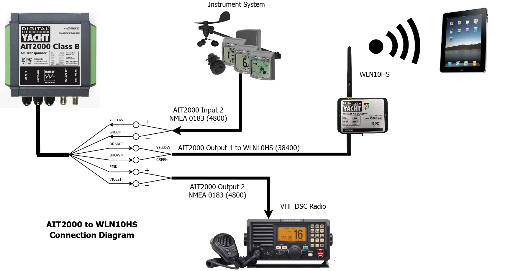
Wiring Details For Wireless Class B Transponder Digital Yacht News
Smartcraft Networking With Humminbird Si Units
Smartcraft Nmea 2000 Gateway Looking Good Panbo