Tbs Crossfire Micro Wiring Diagram

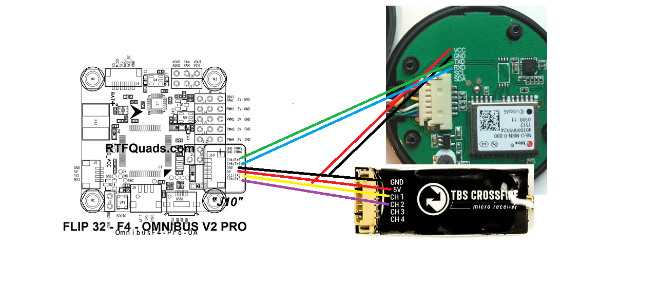
Tbs crossfire micro receiver v2 wiring to fc.
Tbs crossfire micro wiring diagram. The tbs crossfire is a popular rc system for long range flying. If you have a tbs evo you can configure it to allow osd configuration using your radio sticks. How to wire your teamblacksheep microrx v2 to a betaflight controller to use the crsf protocol my social media places. For omnibus f4 pro with bmp baro current sensor and sd card use omnibusf4pro target led strip on.
Open the tbs agent x and connect your tbs evo to your computer via micro usb. T b s c r o s s f i r e r c s y s t e m revision 2019 03 24 a d a p t i v e l o n g ra n g e re mo t e c o n t r o l s y s t e m the tbs crossfire xf system is a r c link system made for fpv enthusiasts. Krohsis i will not comply. Wiring the crossfire micro v2 receiver to fc.
You can now configure your crossfire nano rx and tbs vtx from your radio. Open opentx osd qx7 rapidfire receiver rx rx module smart audio solder taranis tbs tbs fusion uart unify pro32 nano unlock update vtx wiring x lite x9d. It s an external rf module that can be installed directly on the back of the taranis and nirvana so you can still use the powerful opentx interface. Wiring diagrams for omnibus f4 pro.
This is probably my favorite usage of components and wring. 14 jun 2020 08 53 am. You have finished wiring and configuring the setup. Tbs crossfire micro receiver gnd 5v ch1 tx ch2 rx ch3 ch4 tbs crossfire micro receiver gnd 5v ch1 tx ch2 rx ch3 ch4 tbs crossfire micro receiver gnd 5v ch1 tx ch2 rx ch3 ch4 speedybee f4 aio.
Icantfly january 10 2019. The crossfire micro tx has a standard jr form factor and works with any radio that supports ppm tbs crossfire tx rx v or higher at the moment the crsf protocol is supported by the following flight controllers fc. How to wire tbs crossfire nano transmitter to a flight controller. What s special about tbs crossfire.
Transmitter power is selectable between 25mw and 100mw and tx status is shown using a rgb led lite behind the push button. The crossfire operates at the 900mhz band the low frequency means excellent signal penetration ability through obstacles. The diagram for the crossfire pinout looks correct as you will be using uart 1. Crossfire nano rx wiring diagram tx1 rx1 tx3 rx3 ports usb vcp identifier configuration ms serial rx uart1 uart2 uart3 115200 115200 115200 115200.


